Beyond Density: Achieving Optimal AM Parameters with Early Mechanical Property Testing
CASE STUDY IN COLLABORATION WITH

Intro
Cost and time constraints have shaped the conventional workflow in Additive Manufacturing (AM) parameter development, separating parameter down-selection from mechanical property assessment. Yet, this method, aimed at discovering optimal parameters, is inherently flawed. It exposes projects to expensive delays and squandered innovation opportunities due to initial data shortages, potentially misleading results, and unexpected material behaviour. Could prioritising mechanical properties from the outset offer a solution, and is such an approach feasible in practice?
Metal additive manufacturing machines offer numerous production parameters that influence the melting and solidification of each printed alloy. For laser powder bed fusion (LPBF) these include laser power, scanning speed, layer thickness, and hatch distance.
To ensure material and part performance, thorough optimisation of these parameters is crucial. However, as each of these parameters can be adjusted independently, effective parameter selection presents a complex, multi-variable challenge. To break it down,
Intro
conventional parameter development is done via a 2-stage process envelope:
Phase 1: Density Screening
Development starts with a screening process in which density is used as the only down-selection criteria. Typically, 20-50 cubes are produced, each with a different set of parameters. In order to keep printing and material costs low, these cubes are deliberately small (1 cm3). Parameter sets that lead to the highest densities are selected, optimised, and taken to phase 2.
Phase 2: Mechanical Property Assessment
Once a parameter set is identified, the focus shifts to mechanical property assessment through uniaxial tensile testing in phase 2. Large qualification builds, incorporating multiple tensile specimens, are produced to gauge whether the density optimised parameters yield satisfactory mechanical performance. It is typically good practice to collect 30 data points per condition for statistical significance and high part confidence. Examples of these qualification builds are shown in figure 1 below.
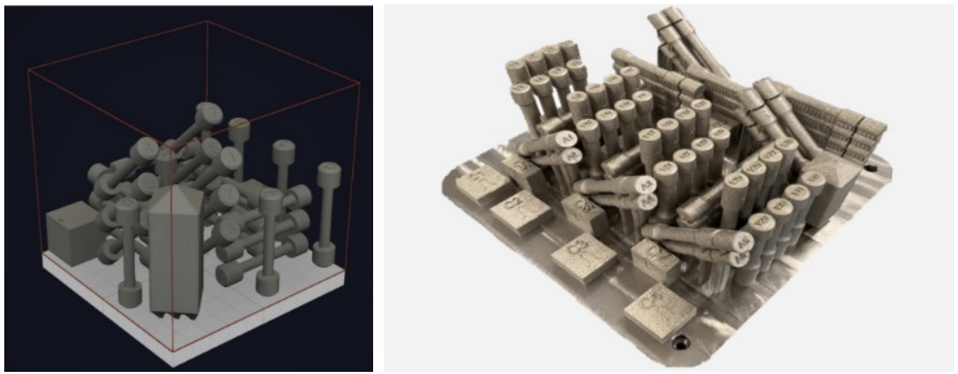
Figure 1: Example qualification builds for (a) an XACT Metal 200C and (b) a Renishaw 500Q
Challenge
Parameter sets determine the thermal history that metals experience during production. This not only influences porosity, it also impacts the microstructure and resultant mechanical properties of the material. Despite this, current parameter development workflows de-couple the measurement of mechanical properties (phase 2) from the early parameter down-selection process (phase 1).
The reason for this is simple; time and cost. A typical tensile coupon has a 30 times higher material volume than a 1cm3 density cube. This extra volume drives up testing time, material and production costs, making the measurement of tensile properties (for a wide range of parameters) both time and cost prohibitive.
This constraint creates two important issues:
Challenge
- A lack of mechanical property data in the early phase of parameter development means important trends between parameters and material properties are being missed. Therefore, optimal parameter sets that demonstrate ideal density and material property combinations are not being uncovered, optimised, and utilised in parts.
- The material properties at the start of qualification testing (Phase 2) are unknown. This creates a severe risk – as it is possible that the material exhibits acceptable density but inadequate material properties for a given application. In this scenario, new parameters must be screened and optimised for another qualification run. A single qualification exercise can cost in excess of £10,000 and take several weeks of engineering time, making a re-do exercise a significant resource drain.
Objectives
In this case study, in collaboration with Additive Manufacturing Solutions, we aimed to determine if PIP (Profilometry-based Indentation Plastometry) testing would enable users to measure stress-strain curves from 1 cm3 density cubes. This would empower engineers and scientists to select optimal printing parameters from a data set that includes both porosity as well the fundamental mechanical properties (yield stress and ultimate tensile strength) of the material. Importantly, in cases where different parameter sets lead to similar density values, PIP testing would enable users to differentiate samples based on mechanical data.
Measurements
Optical density measurements were carried out on images that were taken using a Nikon Eclipse Ci-POL camera, initially by using ILASTIK that applies a machine learning pixel classification method, and ImageJ , to measure the relative area of the pores.
The mechanical properties were measured using the PLX-Benchtop (figure 2), a compact indentation-based benchtop device for PIP testing. PIP uses an accelerated inverse finite element method to infer accurate stress-strain curves from indentation test data.
Materials
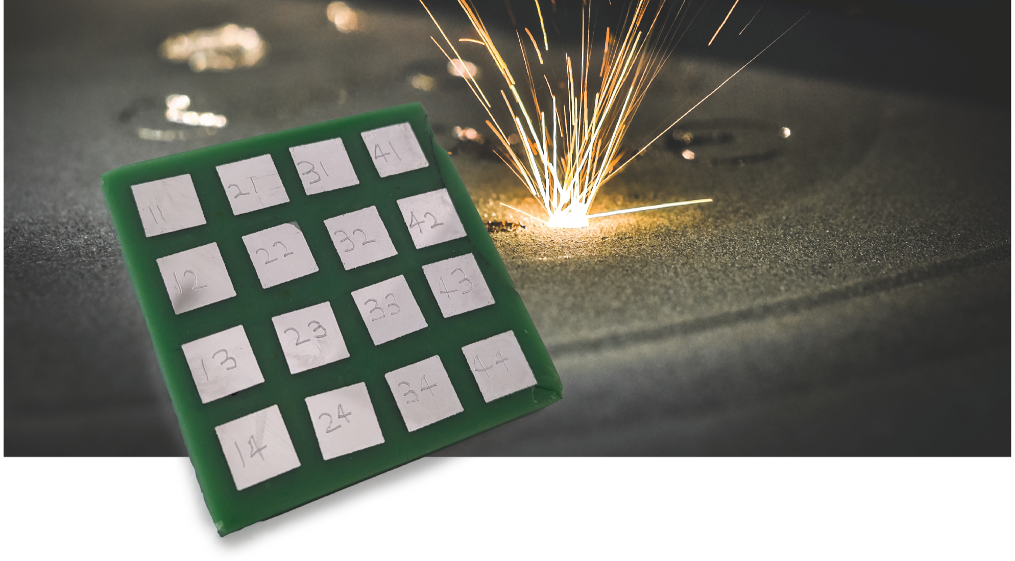
A standard PIP test uses a spherical indenter of 2 mm diameter and indents to a depth in the region of 200 microns. This scale allows a PIP test to be carried out directly on a 1 cm3 density cube. Only a P1200 micron grind (P600 in North American grade) is required for PIP testing and the test duration is in the region of 5 minutes per sample, including sample preparation. In this study, 16 parameter cubes were mounted in cold mount resin into a single sample array block (figure 3). This array could then be prepared on a grinding wheel as a single specimen, reducing the total preparation time to just 10 minutes.
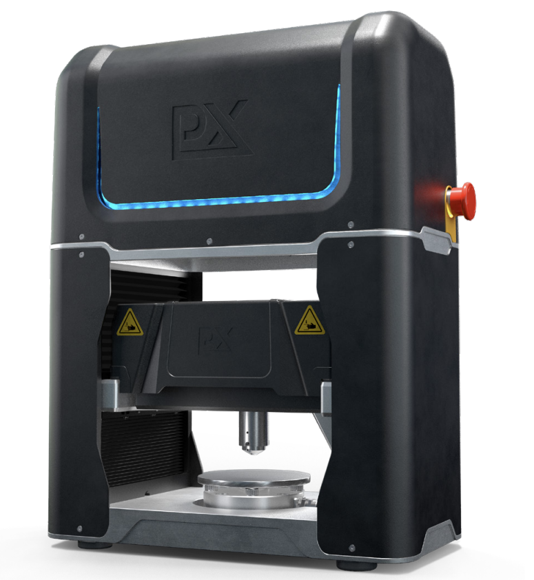
Figure 2: Plastometrex PLX-Benchtop
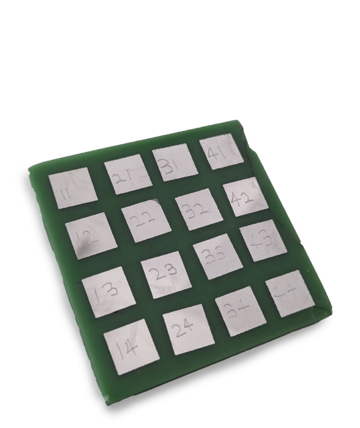
Figure 3: Sample array featuring 16 parameter cubes
Materials
AlSi10Mg was chosen as the example alloy for this work as it is a very common printing material, thereby requiring its parameterisation on many different machines. The 16 samples studied were produced on an SLM solutions SLM 500 machine. Surfaces for indentation and microscopy were prepared to a 1 μm finish. The printing parameters for the cubes studied were:
- Laser power (W): 400, 475, 550, 625.
- Scan speed (mm s-1): 1650 and 2000.
- Layer thickness (μm): 30 and 60.

Results
The printing parameters adopted in this work were chosen to cover a wide range of potential parameters. Firstly, the layer thickness was varied from 30 μm to 60 μm. This is an important parameter to optimise, as doubling the layer thicknesses equates to approximately halving the build time, which dramatically increases productivity.
Secondly, the parameters contributing to energy density were varied. The energy density window is important as it showcases the factors which provide the sweet spot where the metal is fully melting but not over melting. Energy densities between 19 and 64 J mm-3 were used in this study.
Initial work assessed the density of the cubes produced. All cubes showed similar high densities with 14 of the 16 combinations having a density above 99%, as shown in figure 4. Several parameter sets leading to similarly high densities would make it difficult to confidently establish
Results
which had optimal properties without mechanical data. However, if tensile testing was being used to establish their mechanical properties, then a substantial number of tensile testing coupons (for each parameter set) would need to be printed at significant cost and time. Here, the 14 density cubes with porosity below 1% are already in a suitable condition for PIP testing, which requires just a flat parallel surface and minimal surface preparation. (In fact, the surface preparation requirements are less onerous than those required for the optical measurements of porosity.)

Figure 4: Plot of measured optical density as a function of energy density for the 16 different parameter combinations that were explored.
PIP testing was carried out on the samples in this work to assess their mechanical properties – namely yield and tensile strength, although full stress-strain curves emerge from the tests. A plot of yield strength and ultimate tensile strength (UTS) against energy density is shown in figure 5, for the 14 samples with a measured density above 99%.
This plot demonstrates that the energy density has a significant effect on the mechanical properties (yield and tensile strength). Changing the processing conditions by varying the laser parameters and layer thickness result in different melting and solidifications conditions for each case, which changes the microstructure and ultimately results in different mechanical properties.
For each layer thickness studied, both the yield strength and ultimate tensile strength decrease as the energy density increases. As the energy density increases, larger melt pools will be produced (and likely more re-melted layers) so solidification time increases creating a coarser microstructure which negatively impacts the mechanical properties.
The plot also illustrates that even small differences in yield and tensile strength can easily be resolved between the samples. In addition, approximately equivalent mechanical properties (yield and tensile strength) can be obtained at both low and high energy density, by adjusting the layer thickness. With this knowledge operators have the necessary information to now optimise the build for both time and cost saving, by utilising the larger layer thickness to reduce build time while still achieving optimum mechanical properties.
"Even for samples above 99% density, the ultimate tensile strength variation is almost 20% while the yield stress variation is greater than 45%"
Finally, with all of the samples in figure 5 achieving densities of over 99%, this demonstrates that similar porosity values should never be used to infer similarities in mechanical properties. The mechanical properties will depend on other microstructural features such as phase fractions and grain size, not just the porosity fraction. In this case, even for samples above 99% density, the ultimate tensile strength variation is almost 20% while the yield stress variation is greater than 45%.
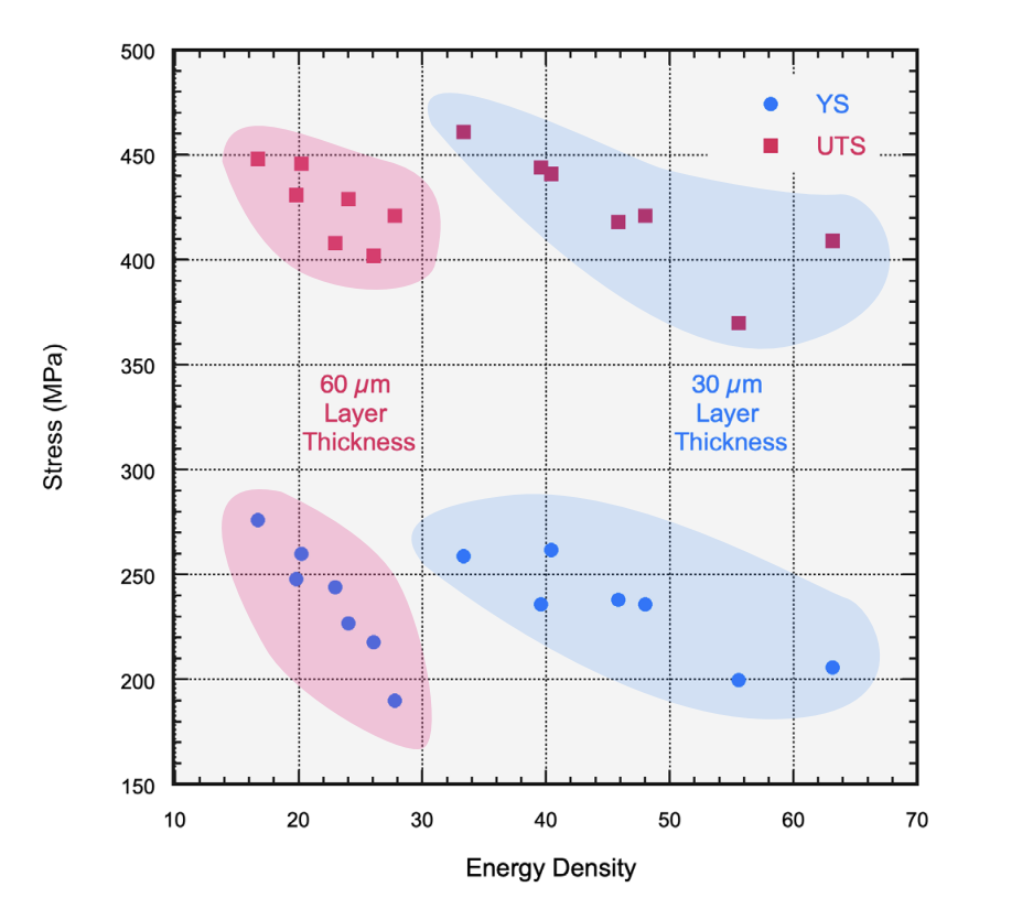
Figure 5: Plot of yield strength and UTS as a function of energy density for the 14 different parameter combinations that were explored.
Outcomes
PIP testing has successfully unlocked the ability to measure stress-strains curves directly from the 1cm3 density cubes used in parameter development. This enables users to down-select parameters based on the optimal combination of strength and density early in the development process, an exercise that was previously cost-prohibitive. This work also shows that different parameter sets that lead to similar density values can exhibit very different mechanical properties. This suggests that density should not be used as the only down-selection criteria in cases where material strength is important.
Without PIP testing this assessment would require dozens of tensile testing coupons to be printed in large builds, costing tens of thousands of pounds, whereas in these experiments the cost of testing has been reduced by ~95%, and the printing time reduced from over 46 hours to 9 hours.
Outcomes
This cost reduction allows testing that typically otherwise is not being performed.
Incorporating PIP testing into the parameter development process affords a distinct competitive advantage, enabling manufacturers to rapidly identify and leverage optimal material properties. By advancing this more informed and efficient approach to parameter development, companies can expect to achieve a marked enhancement in their operational efficiency and product quality, solidifying their competitive edge in the rapidly evolving AM sector.
So, what does this mean for “best practice” in AM parameter development? Join AMS CEO, former Airbus engineer, and all-round AM expert, Rob Higham, and materials scientist and Plastometrex CTO, Dr Jimmy Campbell, for their upcoming webinar as they discuss the challenges of parameter development, how the findings from this study could present an opportunity for users, and whether a change in approach could work in practice.
WEBINAR ON-DEMAND
The AM Density Deception: Navigating Risks in Parameter Development
When: On-Demand
Hosted by: Dr Jimmy Campbell (CTO, Plastometrex) & Rob Higham (CEO, Additive Manufacturing Solutions)
This webinar covers:
- The challenges with current parameter development best practice, including the risks associated with reliance on density.
- Real-world examples of these challenges and their impact on the product development process.
- The findings of our recent joint case study with AMS and how these findings may influence current best practices.
Click the button below to tune in.
Meet the PLX-Benchtop
The PLX-Benchtop is a mechanical testing device that extracts metal stress-strain curves from indentation test data.
With users reporting up to 99% cost and time savings compared to conventional tensile testing, parameter development for AM has never been easier.

Get in touch!
